docs
Cable splice - Fabrication
Cable preparation, mechanical load transfer, soldering and insulation of the splice.
Cutting and mechanical load transfer
Start by cutting the cable cleanly with a cutting disc. Before cutting, apply a few centimeters of Scotch 33+ at the chosen location to hold the strands in place.
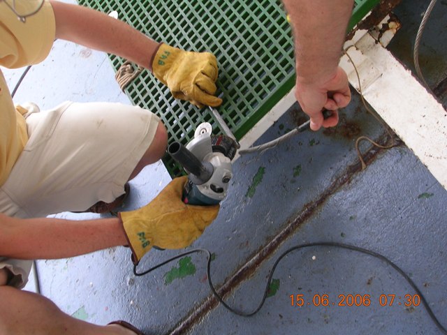
Clean cut of the electromechanical cable, with the strands held in place by adhesive tape.
It can be useful to keep two to three meters of cable available in order to add a safety loop or to keep some rework margin.
Leave about three meters of cable, slide the two parts of the cable grip socket into place, then close the socket in a vise using locking pliers. This step can be difficult on a 10.85 mm cable, which is particularly stiff. Long bolts can help close the socket progressively before replacing them with shorter stainless steel bolts.
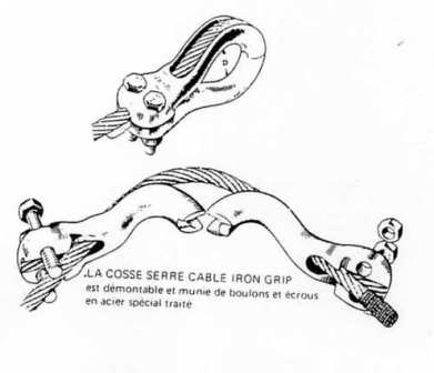
Principle of the cable grip socket used to mechanically take up the cable load.
Then install the claw-type cable grips and form the loops required by the equipment in use: CTD, plankton net or another instrument. The original zinc-plated steel bolts must be replaced with A4 stainless steel bolts.
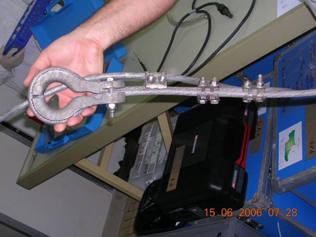
Initial fitting of the socket and mechanical load-transfer grips.
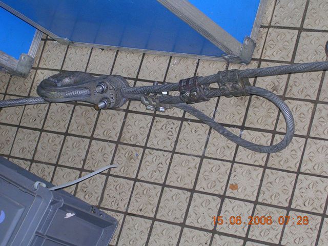
Mechanical load transfer after installation of the cable grips.
Preparing the strands
Carefully degrease the cable. Remove the outer strand wires one by one over about 15 to 20 cm, then cut them progressively without twisting them. Reposition them over the lower strand layer to keep the surface clean and smooth.
This step requires great care. Poorly cut or poorly repositioned wires can encourage water ingress between the strands, or even up to the central core. This degrades cable insulation and accelerates corrosion.
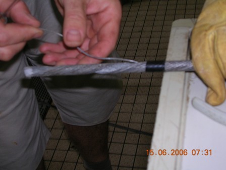
Progressive preparation of the strands before accessing the conducting core.
Then remove the inner strand wires, keeping two or three wires slightly longer. These wires will be used for the solder joint. Also prepare the flexible cable that will power the instrument.
For a Sea-Bird SBE 911+ CTD, prepare the RMG-2FS cable or pigtail by stripping the ends in a staggered pattern. Pay attention to polarity: on these cables, the negative conductor is the white wire and the positive conductor is the black wire. Do not forget to pass the wet-mate connector cap onto the cable before soldering.
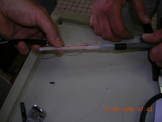
Preparation of the wires kept for soldering and dry fitting.
Cleaning and tinning
The wires intended for soldering can be left for a few minutes in sulfuric acid diluted to 10 %. This operation makes tinning easier, especially on oxidized cables or cables that are difficult to solder.
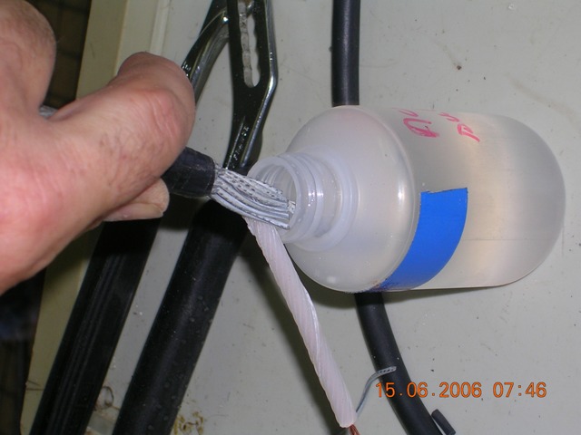
Cleaning the wires before tinning.
After cleaning, wipe the wires, apply soldering paste, then tin them with a thermostatically controlled iron at around 280 to 300 °C.
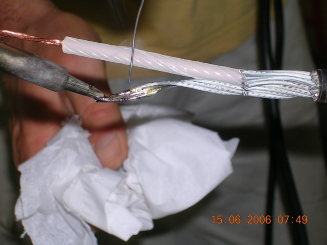
Tinning the prepared wires to make the final soldering easier.
Soldering and checks
Remove the epoxy insulation from the electromechanical cable over about 25 mm. This operation is delicate and must be done without damaging the central core.
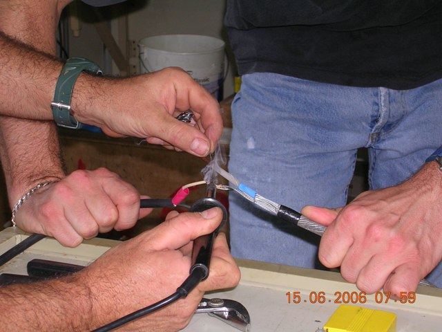
Preparing the soldering area after removing the epoxy insulation.
Slide heat-shrink tubes onto the flexible cable wires, then make the solder joints. The tubes must be ready before final assembly so that each conductor can be properly insulated.
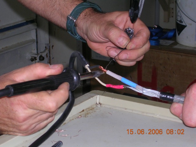
Soldering the conductors between the electromechanical cable and the flexible cable.
Then position the heat-shrink tubes over the solder joints and heat them for a few seconds with a heat gun.
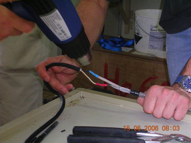
Insulating the solder joints with heat-shrink tubing.
The finished assembly must remain compact, ideally less than 100 mm.
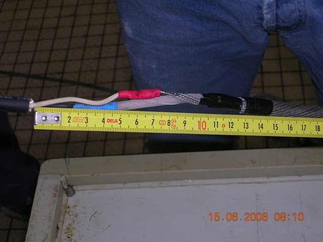
Checking the final dimensions of the soldered area.
Before closing the splice permanently, test the insulation with a megohmmeter with the cable disconnected at both ends, instrument side and deck unit side. The insulation must remain above several megohms. Then check, with no load, that the supply voltage is present on the wet-mate connector, for example 250 V DC for a Sea-Bird CTD. If the voltage is correct, connect the instrument and check acquisition.
Insulating the splice
Switch off the equipment before completing the insulation. First apply a layer of Scotchfil to form a flexible, watertight core around the splice area.
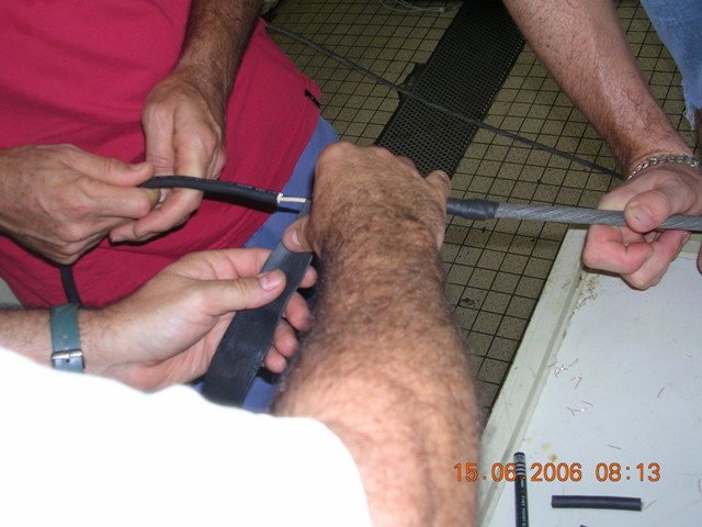
First layer of flexible insulation around the splice.
Then apply two layers of Scotch 23.
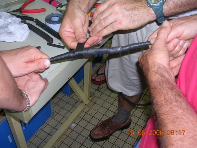
Reinforcing the insulation with two layers of Scotch 23.
Finish with two layers of Scotch 33+, stretching the tape properly.
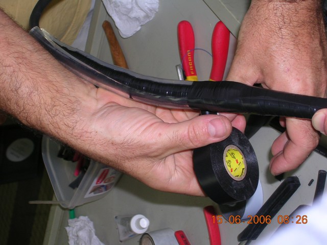
The insulated splice still needs mechanical stiffening.
At this stage, the splice remains fragile. The assembly must be stiffened. The simplest solution is to cut a piece of plastic pipe, slit it lengthwise, then fasten it around the splice with Scotch 33+.
A more professional solution is to use thick-wall heat-shrink tubing with internal adhesive, for example from the SST or SST-FR ranges. This tubing must be placed on the cable before soldering, then positioned after the splice has been closed.
Previous: Bill of materials | Back to documentation | Back to summary | Next: Assembly