docs
Sea-Bird CTD - Test cable and connection
Making a test cable and carrying out basic checks on the electro-mechanical sea cable connection.
Making a test cable
The original guide first emphasizes a simple and very useful point: having a test cable of sufficient length to connect the SBE11+ deck unit directly to the CTD-O2 SBE9+.
This cable makes it possible to quickly check that the CTD package is operating correctly by isolating the CTD from the whole electro-mechanical sea cable + slip ring + splice assembly.
In practice, you need to:
- obtain a
PN 80915 SBE9plus to SBE11pluscable from Sea-Bird - or make a longer test cable if the distance between the deck unit and the CTD requires it
- crimp the
BNCconnectors cleanly if a length adaptation is needed
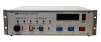
The SBE11 deck unit is the starting point for basic tests and power-supply diagnostics.
Connecting the electro-mechanical sea cable
Before connecting the CTD package, several basic checks are recommended:
- test the insulation and continuity of the electro-mechanical sea cable
- connect the deck unit and use a voltmeter to check for about
250 VDC at the other end - switch off the power
- make the splice if necessary
- check again for
250 VDC on the waterproofRMG-2FSconnector - switch off the power before connecting the CTD
- power up again and check general operation
If there is a problem, power the CTD directly on deck with the test cable in order to isolate the fault origin: either the CTD, or the electro-mechanical sea cable + slip ring + splice assembly.
Previous: Introduction and context | Back to documentation | Back to summary | Next: Fault examples, cables, connectors, and pumps