A few examples of faults encountered in the field, with emphasis on the slip ring, splice, connectors, and pumps.
Published on May 14, 2026
A few examples of faults
The original guide is based on real cases encountered during cruises. This approach is valuable because it shows that the most disabling faults often come from very physical elements of the measurement chain.
Slip ring
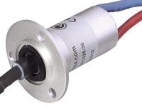
The slip ring provides electrical continuity at the winch between the power supply from the SBE11+ deck unit and the electro-mechanical sea cable. If the solder joint with the sea cable is not made correctly, or if it is subjected to excessive mechanical stress, the conductor can break and cause a clear power failure.
The test cable can then be used to quickly check whether the CTD still works correctly in direct connection. If it does, the fault is very probably in the splice or in the slip ring.
Slip ring, also called a rotating collector.
I have already experienced the following sequence of tests:
insulation and continuity tests are good
CTD power test is correct
then, on the third power-up, nothing: the CTD no longer seems to be powered!
The test cable is then used directly to check that the CTD still works correctly. If it does, the problem is either the splice or the slip ring.
In this precise case, there was probably only one copper strand left on the solder joint between the slip ring and the electro-mechanical sea cable, and that strand must have acted as a fuse on the third power-up!
Short circuit and junction box
A loose screw in the winch junction box can create an intermittent short circuit and severely disturb signal quality. In the event of a hard short circuit, it is usually the sea-cable fuse in the deck unit that blows.
Example of a fault in a junction box linking the slip ring and the electro-mechanical sea cable.
In the event of a hard short circuit, the CTD package power-supply fuse, labelled “sea-cable” on the rear panel of the deck unit, should blow (500 mA fast-blow fuse). It is strongly recommended to keep a substantial stock on board.
intermittent false contacts when moving the splice
correct 250 V DC with no load, but unstable operation as soon as the CTD is connected
Cables and connectors
Cables are among the most sensitive parts of the system. They are numerous, sometimes intrusive, and can vibrate during the down/up profile until they create false contacts. The original guide recommends in particular:
securing cables carefully
favoring 3M 33+ type adhesive tape
avoiding cable ties that damage the neoprene jacket
not leaving any cable loose
not using a cutter to remove adhesive tape during dismantling
Connectors must be cleaned with isopropyl alcohol, the sealing surfaces very lightly greased, and the contacts carefully inspected, especially after immersion or recovery with erratic behavior.
Clean with a lint-free cotton wipe and isopropyl alcohol, then grease very lightly with silicone grease (Parker O-ring or Molykote).
During assembly, the characteristic sound of air being expelled should be heard (plop!).
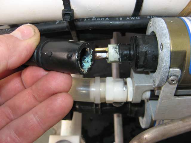
If not, water can enter slightly into the connector during the first meters of the descent and cause slow corrosion.
Example of slow corrosion on a connector.
After a few profiles, and under the effect of pressure, a short circuit can occur randomly during the descent. Everything then works normally once the CTD is back on deck! In this case, disconnect all sensors one by one and check the condition of the connectors, as in the example above.
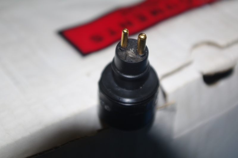
A similar fault can occur with the 2-pin power connector.
The CTD package power supply is 250 V DC, so an electric arc can occur before the fuse blows, leaving carbon deposits between the two contacts.
The connector may look visually sound, but it must be replaced because it is short-circuited. In this case, open the CTD and replace the connector on the upper TAP. Ohmmeter diagnosis is impossible as long as the connector is still connected to the electronics.
Short-circuited 2-pin power connector socket.
Diode D1 on the Sea-cable interface board (SBE9+) may need to be replaced in some cases.
Pumps
The pumps in the T/C/O2 circuits are essential for measurement quality. Pump failures, or false contacts on the Y power cable, often result in degraded, noisy, or inconsistent oxygen profiles.
The original guide also recalls a simple but important point: because the pumps are lubricated by seawater, they must not be allowed to run in air for more than a few seconds.
To test pump operation in the laboratory without immersing the primary sensor in seawater, simply swap the temperature and conductivity sensors of the primary circuit. Connect COND 1 to JB1 and TEMP1 to JB2. At 20 °C, the output frequency of the temperature sensor is above 4,000 Hz and is enough to start the pump after 60 seconds.
For pump maintenance, see the SBE 5T Pump Maintenance application note on the Sea-Bird website.
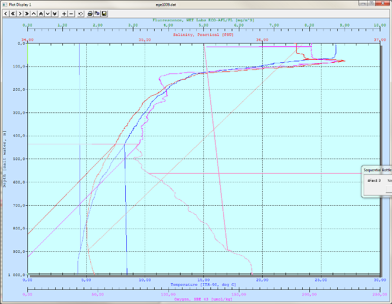
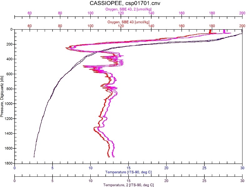
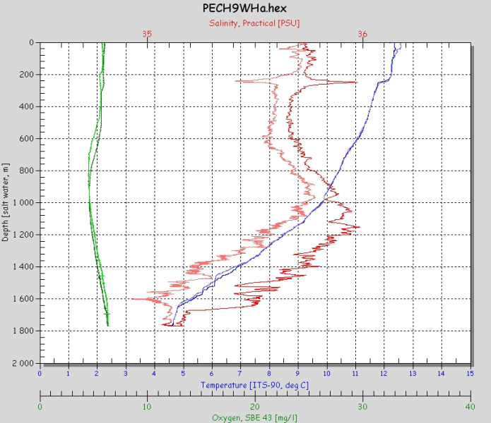
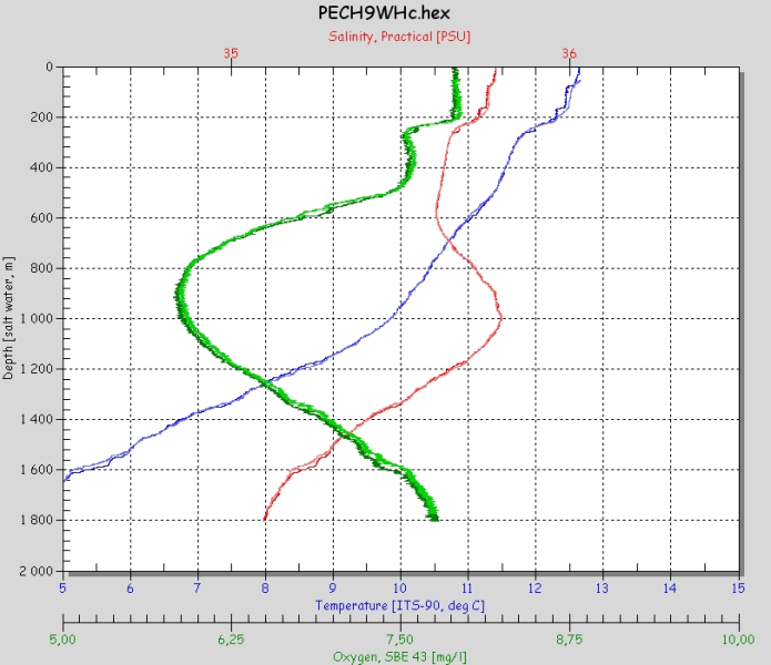
Profile of a correct CTD-O2 station: only a slight absolute offset is observed between the two downcast/upcast profiles and the primary/secondary oxygen sensors, an offset that will be corrected during the adjustment step using bottle samples analyzed by the Winkler method:
Profile of a correct CTD-O2 station.
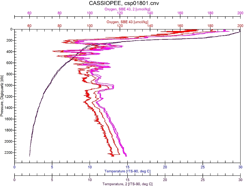
Profile of a CTD-O2 station where a problem is observed on the primary-circuit pump at the end of the downcast profile, around 2,220 dbars.
In this particular case, the primary-circuit pump was successfully replaced for the next profile:
Profile of a station where a problem is observed on the primary-circuit pump at the end of the downcast profile, around 2,220 dbars.
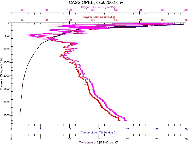
False contact on the Y cable: noisy data are observed at the start of the profile.
Profile with a false contact on the Y cable.
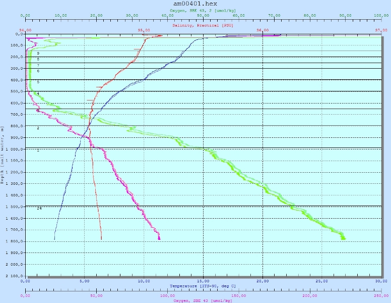
Inversion of the oxygen-sensor calibration coefficients: the profiles have similar shapes, but very different absolute values.
Inversion of the oxygen-sensor calibration coefficients.
One last example shows what happens when water does not circulate correctly through the sensors. Here, the cap protecting the pumping circuit between two stations was accidentally left in place.
Cap protecting the pumping circuit between two stations accidentally left in place.
The result on the same station with a new profile without the cap!